10 i 2 21 i 1 07 --- 1 By applying KVL in loop 2 10 i 2 10 i 2 i 1 10 0. Its wires are separated by 3 cm and their radii are 1 mm each.

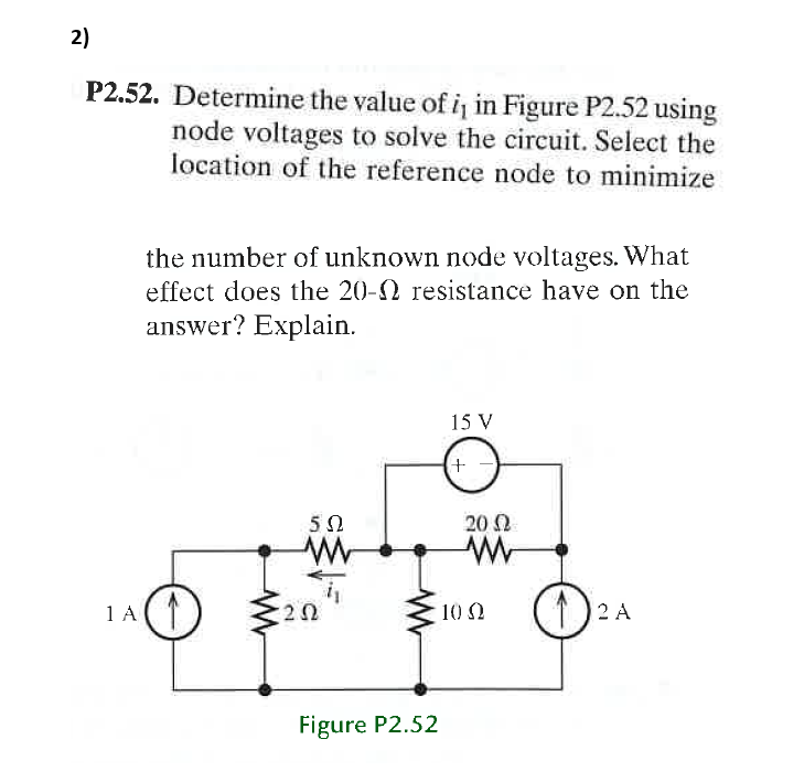
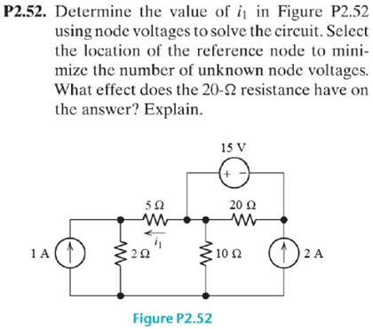
Solved 2 P2 52 Determine The Value Of I In Figure P2 52 Chegg Com
Determine the value of R.

. You will have two unknown voltage nodes as a properly placed reference node will cause one of your nodes to be 0V. 3Hambley P227 Find the voltage v and the currents i 1 and i 2 for the circuit shown in Figure P227. Circuit for Problem 2 3.
Find the value of R. Determine the value of i1 in Figure P254 using node voltages to solve the circuit. Find the currents i1 through i4 and the voltage vo in the circuit in Fig.
All four resistors have the same value R. 04 A V 1 100 I. So we also know v a.
I VS V S v b R 1 V S v c R 4 V S v b R 1 v c v b R 3 v b R 2 V S v c R 4 I S v c v b R 3 v b R 2. Solve for the actual value of i_6 for the circuit of Figure mathrmP 2100 starting with the assumption that i_61 A. 1 kΩ Vo 12 kΩ Figure P282 54 kΩ 72 kΩ 283 Calculate VAB in Fig.
How long is it. Find the currents I1 and I0 in the circuit in figure using currentdivision. A short summary of this paper.
The Attempt at a Solution I went around counterclockwise for both loops and came up with. P246 such that VI Ion 20 v Figure P246 20 n toov 245 The 100-V source in the circuit in Fig. Determine the waveform for voltage across the inductor.
Use mesh analysis to compute the voltage in Figure 380. 7 50 200 25 0. 20 Full PDFs related to this paper.
Let i 1 and i 2 are in mA. Find the voltage Vo in the circuit of Fig. All four resistors have the same valueR.
246 Find the value of in Fig. P245 is supplying 200 W. Use nodal analysis to compute the voltage in the circuit of Figure 378.
It mA o -12 Figure P634 1 2 3 4 5 6 t ms 620 The waveform for the current in a 50-11F initially uncharged capacitor is shown in Fig. Select the location of the reference node ground to minimize the number of unknown node voltages. You will not need to use a super-node.
10i2 i1 20i2 i3 20i2 0 10i3 i1 5i3 20i3 i2 0 Simplifying and solving we find i1 23276 A i2 09483 A and i3 12069 A. Figure P285 5 kΩ 286 Determine the power supplied by the 36-V source in the 18 mA 3 kΩ 30 mA circuit in Fig. 343I1 - 343I2 -113I2 -6 When I solved for that I got Incorrect I1755A I27A.
6Q Figure P233 P234. 2007 The McGraw-Hill Companies Inc. P252 Given R 1 15 Ω R 2 5 Ω R 3 20 Ω R 4 10 Ω R 5 8 Ω R 6 4 Ω and I s 2 A solve for the node voltages shown in Figure P252.
Download Full PDF Package. 18 kΩ 36 V 72 kΩ 18 kΩ B 3 kΩ VAB 4Ω 4Ω 2Ω 6Ω 4Ω 6Ω 2A 6 kΩ Figure P286 A 2Ω 4Ω 2Ω Figure P283 f287. It mA 10 -10.
4Hambley P232 The 12V source in Figure P232 is delivering 36mW of power. Problem 22 A two-wire copper transmission line is embedded in a dielectric material with εr 26 and σ 2106 Sm. I 9 3 0.
By applying KVL in loop 1 10 i 2 i 1 07 - 11 i 1 0. On this page the calculator allows the user to estimate the diamond value based on Rapaport Diamond prices A diamond is valued by 4 important parameters color clarity cut and carat weight. 50 Ω 25 Ω 100 Ω 9 V _ _ V 1 Figure P252.
The 12-V source in Figure P232 is delivering 36m W of power. Efficiency is defined as the ratio of load power to source powerVS 12 V RS 5 k RL 7 k. Ok so from what I can tell I1I2I3 for this equation.
7 V for all diodes. Figure P23 24 Given the circuit in Fig. 5n 6 A 025 S Figure P24 25 In the network in Fig.
Circuit for Problem 252. Assume V F 0. Find the value of R.
In the circuit shown in Figure P234 determine theterminal voltage of the source the power supplied tothe circuit or load and the efficiency of the circuitAssume that the only loss is due to the internalresistance of the source. The four equations now have only 3 unknowns we have the luxury of choosing which equations to solve to find the remaining unknown quantities. Determine the waveform for the capacitors voltage.
Then find the value of i s. On the other hand with the switch closed we have v2 6V. Work back through the circuit to find the value of I_s that.
Finally we have ib i2 - i3 -02586 A. By the definition of a voltage source v a v d V S 0 V S V S. Figure P22 23 Determine the voltage across the resistor in Fig.
P253 Solve for the node voltages shown in Figure P253. Determine the values of R2 and RL. Problem 21 An AWG-14 copper wire has a resistance of 171 Ω at 20 C.
AWG-14 has a diameter of 16 mm Table 2-2 and at 20 C coppers conductivity is σ 581 107 Sm Table 2-1. The estimate of the diamond price is only indicative the prices vary with the market and other factors. Loop 1 113I2 213I1 24 Loop 2 343I3 - 113I2 -6 To get common Is I subbed I1 - I2 in for I3 So Loop 2 becomes.
Figure 352 Chapter 3 Solution 3 Applying KCL to the upper node 10 60 v 2 30 v 20 v 10 v 0 o o 0 v 0 40 V i1 10 v0 4 A i 2 20 v0 2 A i 3 30 v0 13333 A i 4 60 v0 6667 mA PROPRIETARY MATERIAL. Immediately know the value of v a. P2 A find the voltage across each resistor and the power dissipated in each.
R 12 v R R R Figure P232 P233. 3112Figure 3112 For Sweet Dream Hotel has labor costs that are mostly fixed including registration. The equivalent resistance between terminals a and b in Figure P232 is R ab 23W.
12 v With the switch open we have v2 8V. 2 i 2 i 1 1 --- 2 From equations 1 and 2 i_1 frac 43 160mA. Use nodal analysis to compute the current through the resistor and the power supplied or absorbed by the dependent source shown in Figure 379.
Refer to the circuit shown in Figure P233. P23 and the power dissipated. Figure P655 634 The current in a 10-mH inductor is shown in Fig.
The power absorbed by Rx is 20 mW. P251 Given R 1 4 Ω R 2 5 Ω R 3 8 Ω R 4 6 Ω R 5 8 Ω and I s 4 A solve for the node voltages shown in Figure P251.

Solved Determine The Value Of I1 In Figure P2 52 Using Node Chegg Com

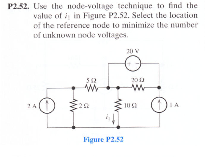
Solved Use The Node Voltage Technique To Find The Value Of Chegg Com

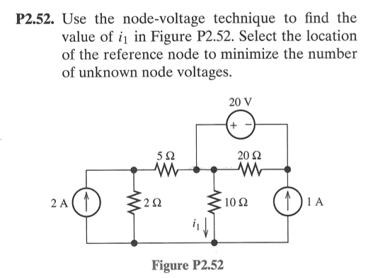
Solved Use The Node Voltage Technique To Find The Value Of Chegg Com
0 Comments